INDUSTRIAL SIGNAL CONDITIONING & PRECISION DAQ[email protected]
LOADCELLAMPLIFIERSmV/V TO MEANINGFUL DATARequest Quote ↗

INDUSTRIAL SIGNAL CONDITIONING / ENGINEERING REVIEW

Panel Meters, OEM Boards & Wireless Load Cell Interfaces

Engineering selection guide · Reviewed 31 October 2026

Define requirements for panel displays, OEM conditioning boards, hazardous-area interfaces and industrial wireless measurement chains.

EXTENDED MEASUREMENT-CHAIN REQUIREMENTS

Define the missing display, board or wireless link.

These are configuration-review categories. Send the existing equipment reference and application constraints so availability, qualification and integration scope can be established in a written offer.

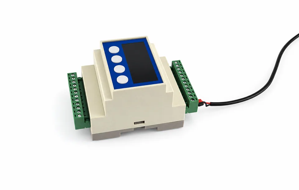
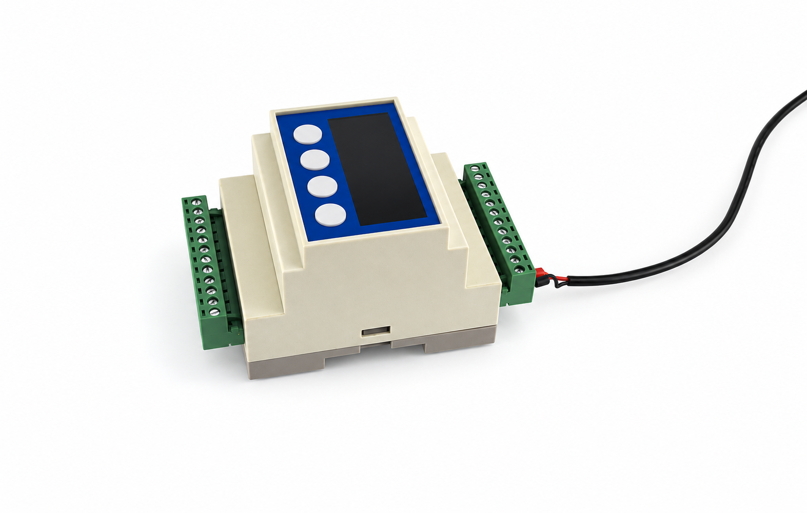
The reference image illustrates a supplier-derived indicator form factor. It does not establish a specific panel opening, firmware function or certified rating.

din rail load cell digital controller gray case blue face four round buttons black attached cable
Supplier-derived product reference, edited from an authorized source photograph. Exact variant, interfaces and specifications require confirmation.Source-derived image ↗

MT-AMP-PCB / CONFIGURATION REVIEW

OEM and replacement-board review

For embedded conditioning or a trim/surge-board replacement: provide board outline, mounting holes, input/output, supply, isolation boundaries, connectors and environmental constraints. OEM industrial boards are reviewed separately from low-cost maker modules.

Request this configuration review ↗

MT-AMP-EX / CONFIGURATION REVIEW

Hazardous-area interface requirements

Provide the applicable site classification, sensor/entity information, wiring and assessment requirements to the responsible qualified engineer. No ATEX/IECEx certificate or intrinsically safe system approval is claimed for an unspecified MT-AMP variant.

Request this configuration review ↗

MT-AMP-WLS / CONFIGURATION REVIEW

Wireless measurement-chain review

Specify force bandwidth, latency, packet-loss behavior, power, operating environment and required receiving output. Confirm region-specific radio compliance, link conditions and the selected transmitter/receiver together.

Request this configuration review ↗
BRIDGE COMPATIBILITY

4-wire or 6-wire?
Start at the bridge.

Match terminals by function and the sensor datasheet. Wire colors and connector pinouts vary by manufacturer.

A 6-wire connection measures excitation at the bridge through separate sense leads. A 4-wire sensor uses excitation and signal pairs; follow the amplifier manual for local sense links.

Strain gauge full bridgeAmplifier input
+ExcitationE+
−ExcitationE−
+SignalS+
−SignalS−
+SenseSEN+
−SenseSEN−
Shield / GNDCHASSIS

Dashed sense lines: 6-wire option. On a 6-wire sensor feeding a 4-wire input, the sensor manual may require sense-to-excitation links of matching polarity. Never infer pin numbers or wire colors. Shield termination follows the installation and EMC plan, not a universal signal-ground jumper.

4-wire sensor → sense-capable input

Connect E+/E− and S+/S− by function. Where the amplifier manual requires local sense links, link SEN+ to E+ and SEN− to E− at its designated terminals.

6-wire sensor → remote-sense input

Run separate SEN+/SEN− feedback conductors to the matching sense terminals. Retain separate excitation and signal pairs; use the model-specific instructions for any local links.

Functional diagrams only. Confirm excitation (including a requested 5V/10V option), maximum bridge current, shield termination and actual pin assignments before energizing a system. Review the connector and pinout ↗

SELECT BY RECEIVER AND CHANNEL ARCHITECTURE

Load Cell Amplifier Comparison Table

Choose the output, then confirm
the bridge and measurement timing.

Filter amplifier families

Know your mV/V, excitation and bridge count? Calculate the signal and excitation burden ↗

5 of 5 families shown

Family selection targets. Confirm the released model and acceptance criteria in the quotation.
ModelInput Range (mV/V)Output SignalSampling Rate / BandwidthChannelsEnclosureReference for ReviewDirect Quote
MT-AMP-DIN ↗0.5–4.0 mV/V target0–5V, 0–10V, ±5V, ±10V, 4–20mAAnalog bandwidth 1–5 kHz target135 mm DIN rail / aluminumFUTEK IAA100 / IAA200 · HBM RM4220 · Burster 9235Configure RFQ ↗Email this family
MT-AMP-USB ↗mV/V range to confirmUSB to PC · CSV logging requirementUp to 4,800 samples/s target1USB-C / aluminumFUTEK USB220 · Mantracourt DSCUSBConfigure RFQ ↗Email this family
MT-AMP-SUM ↗Matched bridge sensorsSummed mV/V · optional 4–20mA / RS485Passive: no sampling rate2 / 4 / 6 / 8 → 1304 / 316 stainless · IP67 targetHBM VKK · Rice Lake · AnyLoad J-boxConfigure RFQ ↗Email this family
MT-AMP-INL ↗mV/V range to confirm0–5V, 0–10V, 4–20mA or RS485 optionsBandwidth to confirm1Ø12 × 55 mm tube / IP67 targetFUTEK ICA family · Interface in-line amplifiersConfigure RFQ ↗Email this family
MT-AMP-BUS ↗Per-channel bridge inputRS485 Modbus RTU / CANopen / EtherCAT optionsRate & synchronization to confirm1 / 4 / 8 independentIndustrial DIN railHBM ClipX / PMX · Siemens SIWAREXConfigure RFQ ↗Email this family

Analog bandwidth differs from sample rate. Passive summing has no sample rate. Original equipment references identify a review path; mechanical, electrical, software and calibration equivalence is model-specific.

COMPLETE THE ENGINEERING HANDOFF

From bridge wiring to sample acceptance.

ENGINEERING / RFQ

Tell us what
your PLC needs.

Share your sensor sensitivity, interface and acquisition speed. We will review the bridge, signal chain and integration requirements before quoting. Attach a sensor datasheet or pinout to the form, or send it with your email.

[email protected]
Sensor + amplifier bundles

Request a complete measurement chain and 5-point system calibration. Include the sensor capacity, force direction and acceptance criteria.

Download the interface review workbook (PDF) ↓

Planning checklist and blank acceptance record. Model datasheets and test certificates are confirmed with your quotation.

Industrial RFQ details and reference files

Review request: Panel Meters, OEM Boards & Wireless Load Cell Interfaces

PDF, PNG or JPEG · up to 2 files · 4 MB each. Files go only to our inquiry team.

0 of 2 reference files selected.

Add bridge, receiver and installation details (optional)

Known values help us review the exact configuration. Leave unknown items blank and attach the original datasheet where available.

Complete your measurement chain

By submitting, you agree to our privacy policy. Options, pricing, calibration scope and delivery are confirmed in your quotation.