Connector appearance does not establish electrical compatibility. A cable assembly review needs the mating parts, the pin-view orientation and the function assigned to every conductor.
M12: coding, contact count, male/female, straight/right-angle and locking arrangement.
DB9: contact numbering, plug/socket, shield shell and any non-standard assignment.
Binder / Molex: exact manufacturer series and mating part numbers.
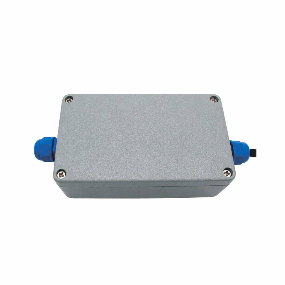
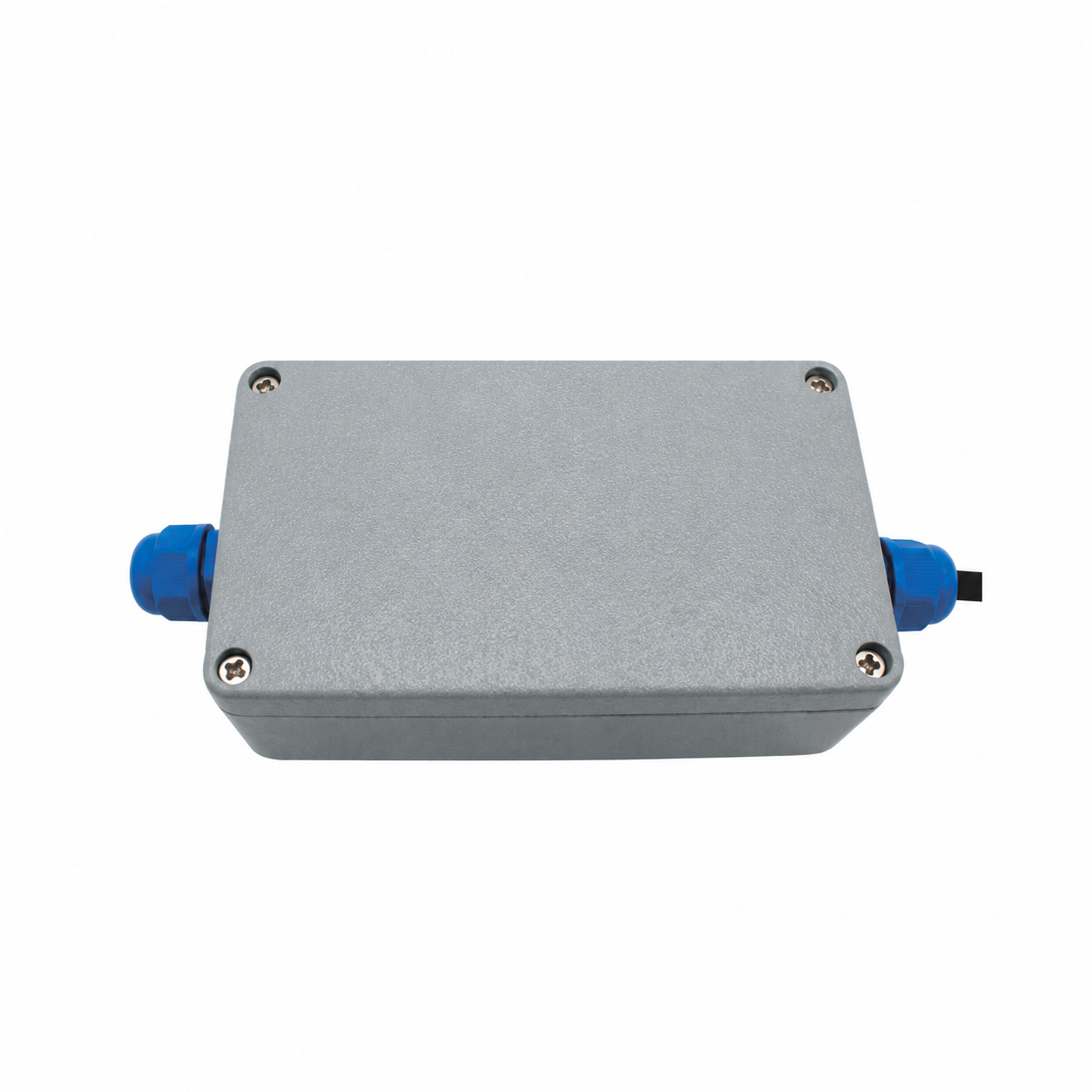
Supplier-derived product reference, edited from an authorized source photograph. Exact variant, interfaces and specifications require confirmation.Source-derived image ↗
Keep sense, excitation and shield assignments explicit.
Provide E+/E−, S+/S−, any SEN+/SEN− and chassis/shield connections. Verify whether the drawing is viewed from the mating face or wiring side. Use the supplied model instructions for local sense links.
A sensor can be electrically suitable while its connector is incompatible. Define any adapter harness as a separate, revision-controlled item.
TEDS is a model-specific integration requirement.
If IEEE 1451.4 electronic sensor identification is required, provide the sensor/TEDS documentation and the fields the receiving system must read. Confirm memory interface, supported templates and configuration behavior for the proposed conditioner.
TEDS support is not assumed for every MT-AMP family. It does not replace checking sensitivity, excitation limits, capacity and calibration.
BRIDGE COMPATIBILITY
4-wire or 6-wire? Start at the bridge.
Match terminals by function and the sensor datasheet. Wire colors and connector pinouts vary by manufacturer.
A 6-wire connection measures excitation at the bridge through separate sense leads. A 4-wire sensor uses excitation and signal pairs; follow the amplifier manual for local sense links.
Strain gauge full bridgeAmplifier input
+ExcitationE+
−ExcitationE−
+SignalS+
−SignalS−
+SenseSEN+
−SenseSEN−
Shield / GNDCHASSIS
Dashed sense lines: 6-wire option. On a 6-wire sensor feeding a 4-wire input, the sensor manual may require sense-to-excitation links of matching polarity. Never infer pin numbers or wire colors. Shield termination follows the installation and EMC plan, not a universal signal-ground jumper.
4-wire sensor → sense-capable input
Connect E+/E− and S+/S− by function. Where the amplifier manual requires local sense links, link SEN+ to E+ and SEN− to E− at its designated terminals.
Run separate SEN+/SEN− feedback conductors to the matching sense terminals. Retain separate excitation and signal pairs; use the model-specific instructions for any local links.
Functional diagrams only. Confirm excitation (including a requested 5V/10V option), maximum bridge current, shield termination and actual pin assignments before energizing a system. Review the connector and pinout ↗
SELECT BY RECEIVER AND CHANNEL ARCHITECTURE
Load Cell Amplifier Comparison Table
Choose the output, then confirm the bridge and measurement timing.
Analog bandwidth differs from sample rate. Passive summing has no sample rate. Original equipment references identify a review path; mechanical, electrical, software and calibration equivalence is model-specific.
Define panel, board, hazardous-area and telemetry requirements before selecting a qualified variant.
ENGINEERING / RFQ
Tell us what your PLC needs.
Share your sensor sensitivity, interface and acquisition speed. We will review the bridge, signal chain and integration requirements before quoting. Attach a sensor datasheet or pinout to the form, or send it with your email.